
Small Drives Applications
Any electrical system requires current sensors at various stages of its operation. These current sensors detect and measure electrical parameters. Depending on their location, role, and specifications, they ensure optimized and safe operation of the system itself. This also applies to small or low-current drive applications, such as air conditioners, heat pumps, household appliances, robots, servo drives, etc.
In every small drive system, the power/electrical circuit is based on the same key principles. With the trend towards size and performance optimization, current sensors, and especially ICS, play a key role in those systems. Why ICS? Because these semiconductor current sensors, half the size of a nail, bring the same benefits as regular current sensors: they constantly detect and measure precisely how current flows in electrical applications, and they help system makers solve their problems with their tiny footprint and optimized cost.
To understand the key role ICS can play in small drive systems monitoring, let's have a look at a typical small drive application connected to the grid:
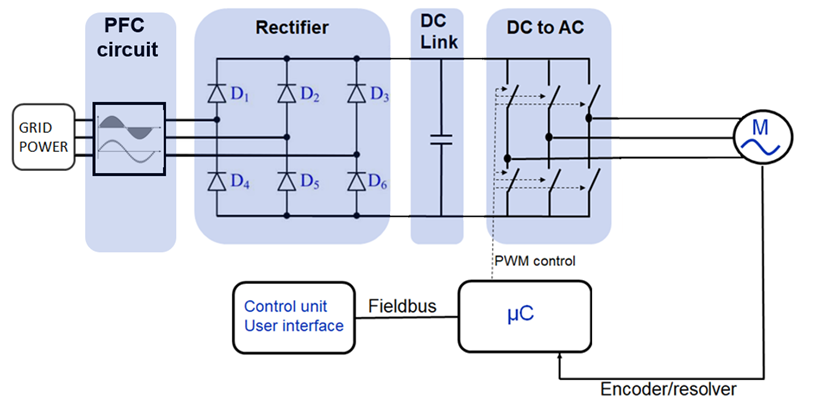
1. PFC (Power Factor Correction) or Active Front-End, the first position for an ICS in a small drive system
In a small drive system connected to the grid, the circuit has to ensure optimum current transmission. Depending on the power load generated by the small drive, altered signals could be found and fed back into the grid. In an optimal electrical system, the signal should look like the red line, but sometimes the electrical signal looks more like a skewed signal like the blue line (see picture).
At this stage in the circuit, the objective is to clean the signal to make it acceptable to the grid and, therefore, compatible with specific grid regulations in force. Here, up to three ICS current sensors can be implemented in this position to detect the current, transfer the information to the system, and regulate the electric signal.
Specifications are usually:
Current up to 30ARMS should be enough
Bandwidth of 300kHz is enough
1% accuracy at 25C
400V/800V basic insulation
In LEM's ICS range, two suspects can perfectly do the job. The best choice in this case is usually GO SME, as it offers an optimized footprint as well as cost-effectiveness. But HMSR can also be the perfect choice if the application requires specific isolation capabilities.
2. ICS in the DC LINK
The DC link part of the system is where the signal is turned into DC. This signal will then be used by the inverter to pilot the motor.
At this stage, the choice of an integrated current sensor is critical because the ICS allows the protection of the system's inverter in case of a short circuit. In this position, the ICS's purpose is to detect the short circuit and communicate the information to the microcontroller. The inverter's IGBT and switches are therefore protected. Generally speaking, the current sensor should be able to handle 300kHz, but the trend is rather to level this value up to 1 MHz to protect the electrical system even faster.
In this position in the system, the ICS is located where the voltage reaches its maximum level (up to 800 V). It's key to choose an ICS offering reinforced isolation.
The specs required at this stage are usually the following:
Current up to 80ARMS
Bandwidth of 300kHz
Fast OCD might be enough for this function
1% accuracy at 25C
400V/800V insulation reinforced
LEM HMSR SMS is the best-fit thanks to its reinforced isolation concept, but GO SMS can also do the job depending on the application-specific requirements.
3. Phase Current Detection
Current sensors are used at this stage in the system to measure the current in the different phases and allow the microcontroller in the system to calculate the speed of the motor and adjust the parameters, if necessary.
It is in this last position that the DC signal transforms into an AC signal thanks to the inverter.
How DC current converts to AC
"The role of the microcontroller is to control the switches so that they open and close when needed. At this stage, the signal on top of the switch is a DC one. Note that the switches are always activated by two.
For current to enter a switch, it must pass through the motor and exit via another switch. The microcontroller will activate the switches 2 by 2, allowing the DC current to enter the motor. In parallel, the motor will run to supply power to the coils and windings, ensuring that the 2 switches work in tandem. When the motor activates 2 of these switches, the current will start to increase. This is when the switches need to be turned off to reduce the current. Note that the current power must be known constantly to determine the motor's effective speed.
The microcontroller plays an essential role in this process: it constantly reads the current to assess its actual speed and informs the motor to optimize its speed if it's not at its highest potential. For example, if the speed is too low, the microcontroller will change the PWF to increase the current flow."
Usually, two to three IC sensors can be used at this stage, depending on the accuracy required and the regulations in force regarding specific applications.
Systems needing high motor speed accuracy, like lifts, industrial robots, or servo drives, will require 1 ICS for each phase.
Specs for most cases at phase current detection stage in small drive systems are:
Current up to 80ARMS
BW of 300kHz should be enough
Fast OCD is appreciated and is enough; no need for high-bandwidth
1% accuracy at 25C
400V/800V insulation reinforced
For servo drives and robots' digital output is the main trend
At this stage in the system, the voltage is the same as at the DC link stage. There is a need for reinforced isolation, and LEM recommends choosing HMSR SMS or GO SMS.
LEM, a World Leader in ICS
LEM has 50 years of experience in current and voltage detection and measurement in various small and large drives. The company has also built a unique proficiency in ASIC design and has naturally started developing an ICS range. These ICSs help cover the growing needs emerging from the mega-trend of electrification. LEM supplies ICS solutions for every stage of an electrical system, even the most demanding, such as drives, heat pumps, solar applications, industrial robots, and servo drives.
The journey doesn't stop here. Further market trends are towards higher current capabilities, increased accuracy over temperature, and faster response time. LEM ICS range keeps growing and constantly adapts to match the diversity of the needs in small drive applications. Stay tuned for the next releases.
ⓒ 2026 TECHTIMES.com All rights reserved. Do not reproduce without permission.


